Learning the Art of Electronics: 19L.1.5 Replace Discrete Logic with Memory
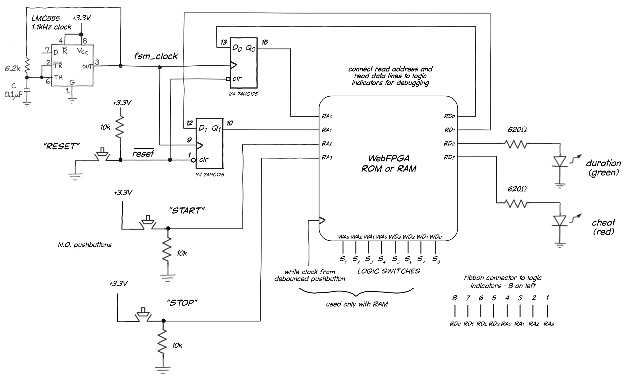
You can replace the discrete gate logic with a RAM or ROM programmed with the PS/NS table. Here is the schematic of our build:

We built it on a separate breadboard so we included an FSM clock source (a LMC555 timer set for a 1.1kHZ square wave). If you build it on the powered breadboard, you can use the built-in function generator (through the 3.3V 74HC40450 level shifter) or an external function generator. If you program the FPGA to be a ROM, you will not need the inputs shown at the bottom of the WebFPGA. However, the advantage of using a RAM is that you can correct errors or change the function of the FSM without the IDE and downloading a new bitstream. The disadvantage is that you must reprogram the RAM anytime you power cycle the FSM.
Here is the memory data for the reaction timer control FSM (based on the PS/NS table in https://LAoE.link/FPGA/19L.1.3_PSNS_Table.html. Since there is no logic to simplify, we assigned states binary values in sequence (A=00, B=01, C=10, D=11).
| stop RA[3] | start RA[2] | Q1 RA[1] | Q0 RA[0] | cheat RD[3] | duration RD[2] | D1 RD[1] | D0 RD[0] |
|---|---|---|---|---|---|---|---|
| 0 | 0 | 0 | 0 | 0 | 0 | 0 | 0 |
| 0 | 0 | 0 | 1 | 0 | 1 | 0 | 1 |
| 0 | 0 | 1 | 0 | 0 | 0 | 1 | 0 |
| 0 | 0 | 1 | 1 | 1 | 1 | 0 | 1 |
| 0 | 1 | 0 | 0 | 0 | 0 | 0 | 1 |
| 0 | 1 | 0 | 1 | 0 | 1 | 0 | 1 |
| 0 | 1 | 1 | 0 | 0 | 0 | 1 | 0 |
| 0 | 1 | 1 | 1 | 1 | 0 | 1 | 1 |
| 1 | 0 | 0 | 0 | 1 | 0 | 1 | 1 |
| 1 | 0 | 0 | 1 | 0 | 1 | 1 | 0 |
| 1 | 0 | 1 | 0 | 0 | 0 | 1 | 0 |
| 1 | 0 | 1 | 1 | 1 | 0 | 1 | 1 |
| 1 | 1 | 0 | 0 | 0 | 0 | 1 | 1 |
| 1 | 1 | 0 | 1 | 0 | 1 | 1 | 0 |
| 1 | 1 | 1 | 0 | 0 | 0 | 1 | 0 |
| 1 | 1 | 1 | 1 | 1 | 0 | 1 | 1 |
We tested this data with a RAM using this Verilog code: https://LAoE.link/FPGA/18L_RAM2P_16X4.v
Here is a Verilog ROM containing the same data:1
//////////////////////////////////////////////////////////////////////////////////
// Company: Learning the Art of Electronics
// Engineer: David Abrams
//
// Create Date:    2/25/2023
// Design Name:    19L.1.5_FF_Memory.v
// Module Name:    REACT_TMR_ROM_FSM
// Description:    Verilog ROM to use with the reaction timer FSM
//////////////////////////////////////////////////////////////////////////////////

//**********************************************
// The comments in this block are directives to
// the WebFPGA environment.
//
// Set name of top level module (default is fpga_top)
// @FPGA_TOP REACT_TMR_ROM_FSM
//
// @MAP_IO rd_addr[3]  25  // STOP switch
// @MAP_IO rd_addr[2]  24  // START switch
// @MAP_IO rd_addr[1]  23  // Q1
// @MAP_IO rd_addr[0]  22  // Q0
//
// @MAP_IO rd_data[3]  21  // CHEAT
// @MAP_IO rd_data[2]  20  // DURATION
// @MAP_IO rd_data[1]  18  // D1
// @MAP_IO rd_data[0]  17  // D0
//**********************************************

// The following form for the module declaration is
// necessary to use parameters in the port definitions
module REACT_TMR_ROM_FSM (
  input      [3:0] rd_addr,
  output reg [3:0] rd_data
);

  always@(*) begin
    case(rd_addr)
        4'b0000: rd_data = 4'b0000;
        4'b0001: rd_data = 4'b0101;
        4'b0010: rd_data = 4'b0010;
        4'b0011: rd_data = 4'b1011;
        4'b0100: rd_data = 4'b0001;
        4'b0101: rd_data = 4'b0101;
        4'b0110: rd_data = 4'b0010;
        4'b0111: rd_data = 4'b1011;
        4'b1000: rd_data = 4'b0011;
        4'b1001: rd_data = 4'b0110;
        4'b1010: rd_data = 4'b0010;
        4'b1011: rd_data = 4'b1011;
        4'b1100: rd_data = 4'b0011;
        4'b1101: rd_data = 4'b0110;
        4'b1110: rd_data = 4'b0010;
        4'b1111: rd_data = 4'b1011;
    endcase
  end
endmodule
Code available at https://LAoE.link/FPGA/19L.1.5_FF_Memory_ROM.v↩︎