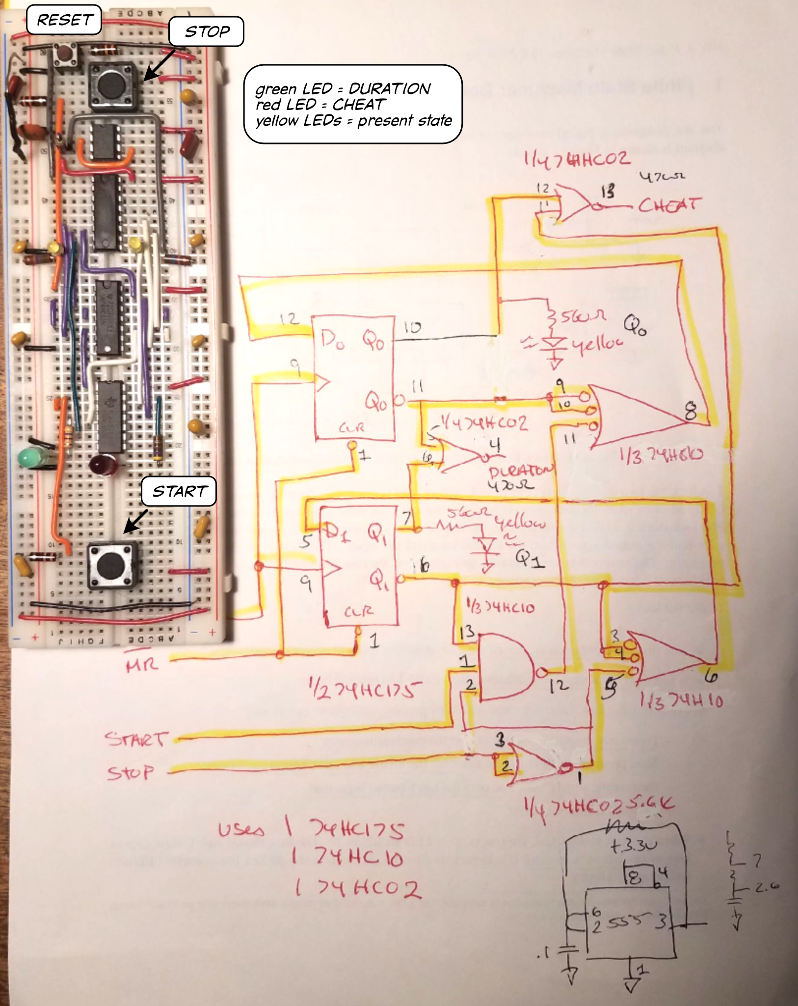
Learning the Art of Electronics: 19L.1.4.1 Build of the Reaction Timer FSM
Additions to the basic FSM of the previous schematic include the input buttons, the output LEDs, two small LEDs on the flip-flop outputs to display state (along with pullup or current liming resistors) and a LMC555 timer to provide the 1.2kHz FSM clock. The 555 must be a CMOS version ( the "C" in the part number) to work on 3.3V.
